September 28, 2023
What Is the Science Behind Push Button Switches and How They Work
Share
BuildWithFlux


A curated collection of PCB and hardware projects crafted by our talented Flux community.
A push button switch is a simple yet versatile electrical switch used to open or close an electrical circuit by pressing a button. These switches come in various shapes and sizes, but they all share the same fundamental principle: pressing the button changes the switch's state from open to closed or vice versa. This action, often accompanied by a satisfying click, completes or breaks an electrical path, enabling or disabling a device's function.

Understanding how a push button switch works requires a closer look at its internal components. Here is a simplified breakdown:
Push button switches can vary significantly in their configurations, and understanding these distinctions is crucial when designing electronic circuits. Here are some common types:
The SPST push button switch is our first type of single pole switch. It is the simplest type, featuring only one set of contacts—ideal for basic on/off functions and is often found in household light switches.
An SPDT push button switch, another single pole switch type, offers two sets of contacts, allowing it to act as a toggle switch between two different electrical paths. This is useful in scenarios where you need to choose between two actions with a single button press.
DPST push button switches have two sets of contacts, each operating independently. They are commonly used in situations requiring two separate circuits to be controlled simultaneously.
Push button switches can be further categorized as latching or momentary. Latching switches maintain their state after being pressed, while momentary switches return to their original state when released. These distinctions are important depending on the intended function of the switch.
One common issue with push button switches is debouncing. When you press or release a button, it can create rapid fluctuations in the electrical signal due to the mechanical nature of the switch. This bouncing generates a series of electrical spikes and dips, making it challenging for the connected circuitry to interpret the intended input accurately. Debouncing is the process of filtering out these erratic signals to ensure a clean and stable transition between states. Achieving this involves employing techniques such as:
In scenarios where users might rapidly press a button, it's essential to filter out unintended or extraneous signals. This can be achieved through electronic circuitry that detects and ignores rapid successive button presses, ensuring that only intentional inputs are registered. Here's how it works:
Pull-up and pull-down resistors play a crucial role in pushbutton switch circuits, especially in microcontroller-based designs. These resistors are used to ensure that the input signal to the microcontroller is in a known state when the button is not pressed.
We see pull-up and pull-down applications in software as well when we set default values or states for variables, flags, or configuration options—specifying how a particular variable or option should behave when it is not explicitly set.
Push button switches find applications in various domains:
In electronic schematics, push button switches are represented using specific symbols. The most common symbols for push buttons include:

Whether you're turning on a light, starting your car, or operating heavy machinery, push button switches play a crucial role. Understanding their science and functionality is essential for anyone working with electronic circuits. So now next time you press that unassuming button, you can understand the intricate science behind it.
A push button switch is a simple yet versatile electrical switch used to open or close an electrical circuit by pressing a button. These switches come in various shapes and sizes, but they all share the same fundamental principle: pressing the button changes the switch's state from open to closed or vice versa. This action, often accompanied by a satisfying click, completes or breaks an electrical path, enabling or disabling a device's function.
Understanding how a push button switch works requires a closer look at its internal components. Here is a simplified breakdown:
Push button switches can vary significantly in their configurations, and understanding these distinctions is crucial when designing electronic circuits. Here are some common types:
The SPST push button switch is our first type of single pole switch. It is the simplest type, featuring only one set of contacts—ideal for basic on/off functions and is often found in household light switches.
An SPDT push button switch, another single pole switch type, offers two sets of contacts, allowing it to act as a toggle switch between two different electrical paths. This is useful in scenarios where you need to choose between two actions with a single button press.
DPST push button switches have two sets of contacts, each operating independently. They are commonly used in situations requiring two separate circuits to be controlled simultaneously.
Push button switches can be further categorized as latching or momentary. Latching switches maintain their state after being pressed, while momentary switches return to their original state when released. These distinctions are important depending on the intended function of the switch.
One common issue with push button switches is debouncing. When you press or release a button, it can create rapid fluctuations in the electrical signal due to the mechanical nature of the switch. This bouncing generates a series of electrical spikes and dips, making it challenging for the connected circuitry to interpret the intended input accurately. Debouncing is the process of filtering out these erratic signals to ensure a clean and stable transition between states. Achieving this involves employing techniques such as:
In scenarios where users might rapidly press a button, it's essential to filter out unintended or extraneous signals. This can be achieved through electronic circuitry that detects and ignores rapid successive button presses, ensuring that only intentional inputs are registered. Here's how it works:
Pull-up and pull-down resistors play a crucial role in pushbutton switch circuits, especially in microcontroller-based designs. These resistors are used to ensure that the input signal to the microcontroller is in a known state when the button is not pressed.
We see pull-up and pull-down applications in software as well when we set default values or states for variables, flags, or configuration options—specifying how a particular variable or option should behave when it is not explicitly set.
Push button switches find applications in various domains:
In electronic schematics, push button switches are represented using specific symbols. The most common symbols for push buttons include:
Whether you're turning on a light, starting your car, or operating heavy machinery, push button switches play a crucial role. Understanding their science and functionality is essential for anyone working with electronic circuits. So now next time you press that unassuming button, you can understand the intricate science behind it.


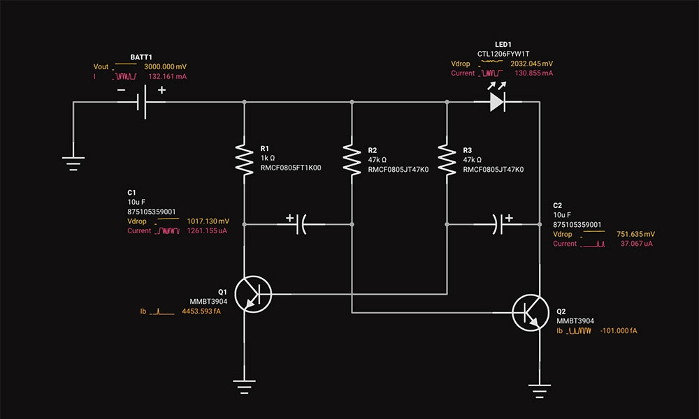
Oscillators are electronic circuits producing oscillating signals without an input. Types include sine, square, sawtooth, triangular, and pulse wave oscillators. Crystal oscillators use vibrating crystals for precise frequencies, crucial in clocks and radios. RF oscillators operate at radio frequencies, essential in broadcasting and telecoms.
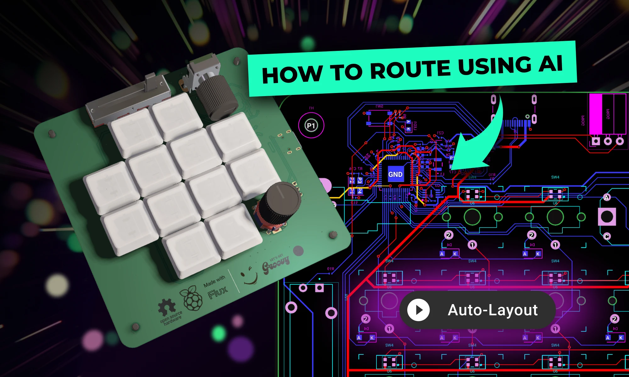
Want to design your own macropad? Discover how to create one using the Raspberry Pi Pico 2 and Flux's AI Auto-Layout. From schematics and components to PCB layout and firmware, we’ve got you covered. Boost your productivity with a custom macropad—start building today!
This blog explores the powerful Arduino map() function, showing you how to scale values, control sensors, and master advanced programming techniques for innovative projects.

The Arduino Pro Micro is a compact microcontroller within the Arduino ecosystem, based on the ATmega32U4. It's ideal for small applications, offering 20 digital I/O pins, built-in USB support, and easy programming. While having some limitations, its flexibility makes it popular for wearables, robotics, and DIY projects.

In this article, we will discuss the key components of the Arduino Uno schematic, including the microcontroller, voltage regulator, USB interface, and passive components, and how they work together to make the board work.
Circuit simulation is a crucial tool in electronic design. It uses software to predict how circuits will perform, saving time and money. Popular options like Flux, LTSpice, and CircuitMaker offer powerful features.
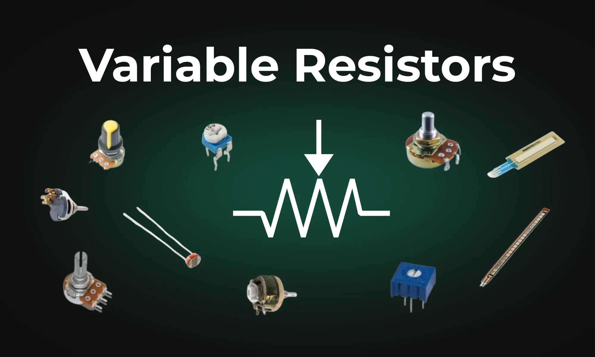
This article provides an overview of six types of variable resistors, including potentiometers, rheostats, photoresistors, wirewound resistors, thermistors, and varistors, highlighting their unique uses in electronic circuits. It also covers advanced applications and emerging technologies like digital potentiometers and memristors, emphasizing their significance in electronic control and adaptability.

KiCad revolutionized PCB design by making it accessible to everyone. Flux builds on that foundation, offering a browser-based, AI-powered platform that takes your PCB design experience to the next level.

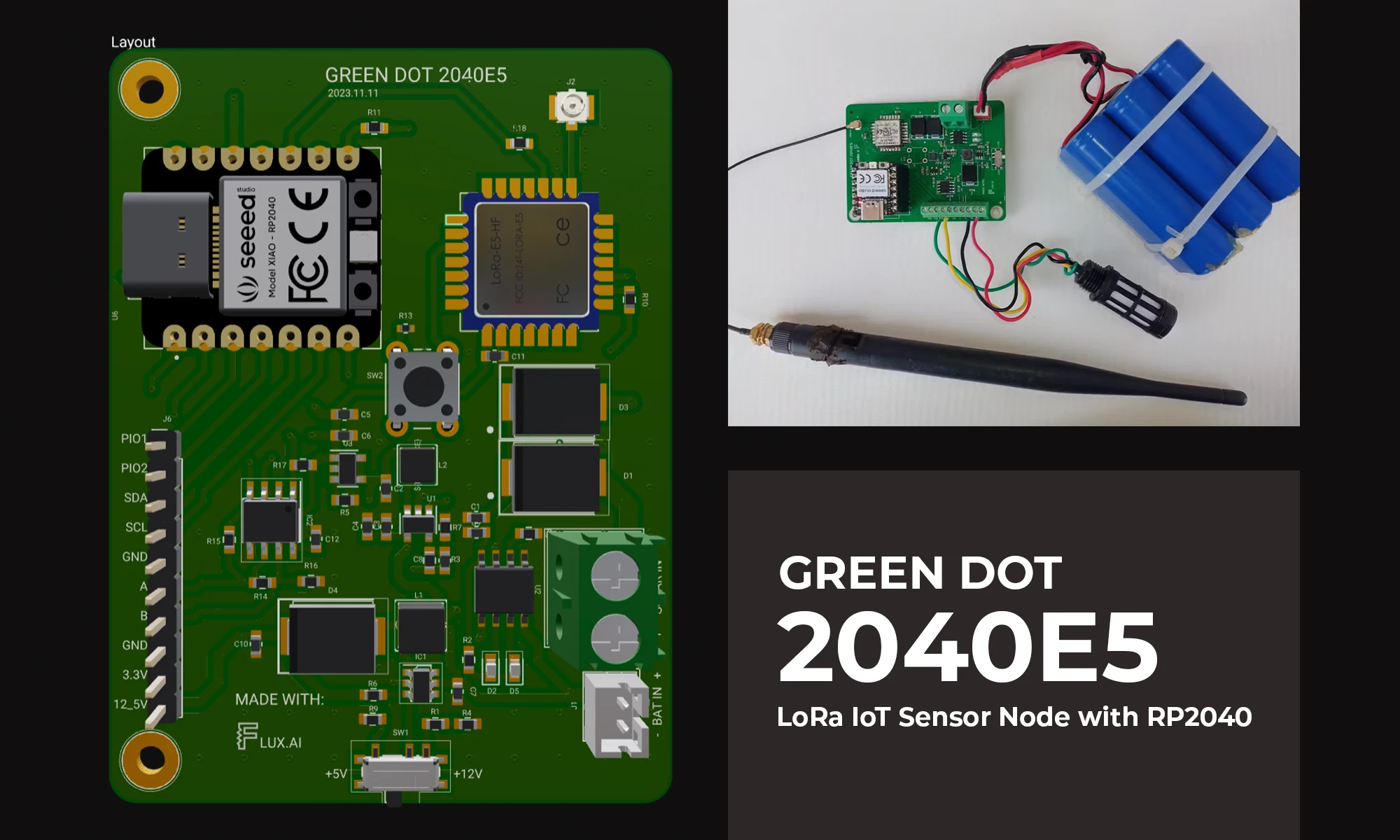
The blog details the creation of a LoRa IoT sensor node for agriculture, focusing on PCB design, power management, wireless connectivity, and sensor integration using the RP2040 microcontroller. It aims to bridge the technology gap in farming, enhancing productivity through data-driven insights.
This blog post explores the diverse mechanisms and applications of voltage regulators, highlighting their significance in maintaining stable voltages in everything from basic electronic circuits to complex systems.

This article provides a comprehensive guide on pull-up and pull-down resistors, emphasizing their importance in establishing a known voltage level on microcontroller pins. It explains how to implement these resistors in Arduino circuits, discussing functions like pinMode and digitalRead. It also dives into real-world applications, voltage dividers, and tips for avoiding common mistakes.

This blog highlights CES 2025 showcased projects, offering insights on how to recreate them using Flux. With Flux AI-driven design tools, component library, and customizable templates, engineers and hobbyists can build inspired hardware like wearables, drones, EV components, portable chargers, and solar devices.